Difference between revisions of "Msc1G2:Student4"
| (22 intermediate revisions by 3 users not shown) | |||
| Line 1: | Line 1: | ||
| + | __NOTOC__ __NOTITLE__ | ||
| + | |||
<html> | <html> | ||
<style> | <style> | ||
| − | div# | + | div#headercontainer { |
| + | width: 850px; | ||
| + | height: 1203px; | ||
| + | margin: 0px; | ||
| + | margin-bottom: -25px; | ||
| + | padding: 0px; | ||
| + | border: 0px; | ||
| + | color: white; | ||
| + | background: white url(http://ex25.hyperbody.nl/images/d/de/Group2_151127_atmosphere_web.jpg); | ||
} | } | ||
| − | div# | + | div#button1 { |
| − | + | float: left; | |
| − | + | width: 155px; | |
| − | + | height: 30px; | |
| − | + | border-left: none; | |
| + | margin-right: 10px; | ||
| + | margin-top: 485px; | ||
| + | background: none; | ||
| + | opacity: 0.8; | ||
| + | } | ||
| + | div#button { | ||
| + | float: left; | ||
| + | width: 155px; | ||
| + | height: 30px; | ||
| + | border-left: 3px solid white; | ||
| + | margin-right: 10px; | ||
| + | margin-top: 485px; | ||
| + | background: none; | ||
| + | opacity: 0.8; | ||
| + | } | ||
| + | |||
| + | div#maintext { | ||
| + | float: left; | ||
| + | width: 600px; | ||
| + | height: 30px; | ||
| + | margin-left: 100px; | ||
| + | margin-top:400px; | ||
| + | align: left; | ||
| + | opacity: 1; | ||
| + | font-size: 120%; | ||
| + | font-style: italic; | ||
| + | letter-spacing: 0.4px; | ||
| + | line-height: 105%; | ||
| + | opacity: 0.8; | ||
| + | } | ||
| + | |||
| + | div#headercontainer a:link {color: white; text-decoration: none; opacity: 1;} | ||
| + | div#headercontainer a:visited {color: white; text-decoration: none; opacity: 1;} | ||
| + | div#headercontainer a:active {color: #ff4da6; text-decoration: none; opacity: 1;} | ||
| + | div#headercontainer a:hover {color: #ff4da6; text-decoration: none; opacity: 1;} | ||
| + | </style> | ||
| + | </html> | ||
<html> | <html> | ||
| Line 16: | Line 63: | ||
== '''Prototype''' == | == '''Prototype''' == | ||
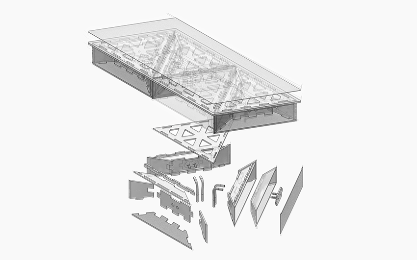
| − | <p> | + | <p>The soft robotic inspired module shows the magnification from a small scale robotic approach to a larger architectural scale. |
| + | To achieve that, the prototype consists of four different parts: A) Soft pneumatic silicon air chambers that are casted in MDF boxes. The silicon chambers are inflated by air and will push each other so that the structure will bend. B) A hard core (3mm MDF), that guarantees the soft parts move in the intended direction. It also stabilizes the the complete shape and allows for it to be assembled easily. C) A 3D printed valve board with an in- and outlet. It is completely infused on the back side of the soft silicon chamber and bridges the connection to the hard wood and the air tubes. It solves the critical part of the sensible connection to the air distribution system. D) A top silicon layer with infused mdf triangles. The MDF secures the connection to the pneumatic boxes and the silicone around it ensures the flexibility of the hinges in between.</p> | ||
<html> | <html> | ||
| − | <iframe width="850" height="531" src="http://raumgewand.de/Hyperbody/ | + | <iframe width="850" height="531" src="http://raumgewand.de/Hyperbody/Prototype/prototype.html" frameBorder="0" seamless="seamless" scrolling="no" allowfullscreen></iframe><br> |
</html> | </html> | ||
| + | <html> | ||
| + | <iframe width="850" height="531" src="https://www.youtube.com/embed/l0fRKRz14qM" frameborder="0" allowfullscreen></iframe><br> | ||
| + | </html> | ||
| + | <html> | ||
| + | <div style="float:left"> | ||
| + | <iframe width="422" height="222" src="https://www.youtube.com/embed/1F-1i-bE7rg" frameborder="0" allowfullscreen></iframe> | ||
| + | <iframe width="422" height="222" src="https://www.youtube.com/embed/7mWYnzOdWF4" frameborder="0" allowfullscreen></iframe> | ||
| + | <iframe width="422" height="222" src="https://www.youtube.com/embed/eW7Zt3Z1omQ" frameborder="0" allowfullscreen></iframe> | ||
| + | <iframe width="422" height="222" src="https://www.youtube.com/embed/TXytAjXgm48" frameborder="0" allowfullscreen></iframe> | ||
| + | </html> | ||
| + | <html> | ||
| + | <iframe width="850" height="531" src="https://www.youtube.com/embed/FoCppFyRJIk" frameborder="0" allowfullscreen></iframe> | ||
| + | </html> | ||
| − | + | [[File:160127_swarmscape_Render_Proto_FINAL.png | 850px]] | |
| − | <i | + | <i>Prototype assembling</i> |
| − | + | ||
| − | + | ||
| − | + | ||
| − | + | ||
[[File: Group2_151215_2ndprototype.jpg | 850px]] | [[File: Group2_151215_2ndprototype.jpg | 850px]] | ||
| Line 39: | Line 96: | ||
== '''Simulation''' == | == '''Simulation''' == | ||
| − | <p> | + | <p>To get the geometry right of as well the prototype and the 3D model we did several tests in Abaqus. To be able to bend up the triangles, the geometry should have a proper relation in height and weight, because the momentum of the bending force (M = F * a) is stated by determined by the height of a triangle side. Upper left shows a constellation of several triangles in silicone, the upper right an earlier version. The bottom left is a simulation of the very first prototype as seen above. On the bottom right the material is changed from silicone to aerogel silicone, this material has small air bubbles embedded in the material and is therefore way lighter than traditional silicone. Although the Youngs modulus and shear modulus have a negative effect on the bending behavior, this material can because of the weight be interesting to research for the interactive architecture practice.</p> |
<html> | <html> | ||
| − | < | + | <div width="850" height="500"> |
| + | <iframe width="422" height="222" src="https://www.youtube.com/embed/qD2uawNJJTI" frameborder="0" allowfullscreen></iframe> <iframe width="422" height="222" src="https://www.youtube.com/embed/8qArr92zcwQ" frameborder="0" allowfullscreen></iframe><br> | ||
| + | </div> | ||
| + | </html> | ||
| − | < | + | <html> |
| − | + | <div width="850" height="500"> | |
| − | <iframe | + | <iframe width="422" height="222" src="https://www.youtube.com/embed/7VFrO4P2msw" frameborder="0" allowfullscreen></iframe> <iframe width="422" height="222" src="https://www.youtube.com/embed/wYyq9ZDF0CU" frameborder="0" allowfullscreen></iframe><br> |
| − | <br> | + | </div> |
</html> | </html> | ||
| − | |||
== '''Setup and arduino code''' == | == '''Setup and arduino code''' == | ||
| + | |||
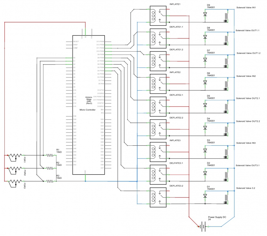
| + | <p> The swarmscape prototype is controlled by a technical board that reads information and tell the prototype how to react. | ||
| + | The board is assembled with simple, low pressure aquarium pumps. These pumps are controlled by solenoid valves which are connected to the silicone structure. To regulate the 24 volt valves, two relay boards and 8 relays are mounted to the board, which are also connected to a Arduino Mega. A second electronic circle with a diode is embedded to prevent short circuits caused by the fall time of the electro magnet (see Setup and arduino code). Additionally, three pressure sensors are connected to the micro controller to process the information to bend up the prototype. </p> | ||
[[File:Group2 20160126 Prototype setup.jpg | 850px]] | [[File:Group2 20160126 Prototype setup.jpg | 850px]] | ||
| + | |||
| + | <p>The code for the prototype needed to be sure that the air chambers at the hinges never get too much pressure, that the sensors work independent of one each other and that the controls are as intuitive as possible. This is achieved by defining the code for several states each sensor can be in accompanied with a timer library. A hinge inflates on the input of a pressure sensor. As long as the sensor is pressed it stays inflated, but when released it stays in position for a time defined by the pressure that is applied. After staying inflated for a while the code goes through a deflation part to be sure the chambers never get too much pressure. Eventually the sensor becomes idle again, waiting for pressure. </p> | ||
<nowiki> | <nowiki> | ||
| − | //sensor.h defenition (used instead of void) | + | //sensor.h defenition (library used instead of void) |
struct Sensor; | struct Sensor; | ||
| Line 273: | Line 337: | ||
} | } | ||
return nextState; | return nextState; | ||
| − | }</nowiki> | + | } |
| + | </nowiki> | ||
== '''Documentation''' == | == '''Documentation''' == | ||
Latest revision as of 17:26, 9 March 2017
Prototype
The soft robotic inspired module shows the magnification from a small scale robotic approach to a larger architectural scale. To achieve that, the prototype consists of four different parts: A) Soft pneumatic silicon air chambers that are casted in MDF boxes. The silicon chambers are inflated by air and will push each other so that the structure will bend. B) A hard core (3mm MDF), that guarantees the soft parts move in the intended direction. It also stabilizes the the complete shape and allows for it to be assembled easily. C) A 3D printed valve board with an in- and outlet. It is completely infused on the back side of the soft silicon chamber and bridges the connection to the hard wood and the air tubes. It solves the critical part of the sensible connection to the air distribution system. D) A top silicon layer with infused mdf triangles. The MDF secures the connection to the pneumatic boxes and the silicone around it ensures the flexibility of the hinges in between.
 1st silicone prototype for pneumatic actuators
 2nd silicone prototype for pneumatic actuators
Simulation
To get the geometry right of as well the prototype and the 3D model we did several tests in Abaqus. To be able to bend up the triangles, the geometry should have a proper relation in height and weight, because the momentum of the bending force (M = F * a) is stated by determined by the height of a triangle side. Upper left shows a constellation of several triangles in silicone, the upper right an earlier version. The bottom left is a simulation of the very first prototype as seen above. On the bottom right the material is changed from silicone to aerogel silicone, this material has small air bubbles embedded in the material and is therefore way lighter than traditional silicone. Although the Youngs modulus and shear modulus have a negative effect on the bending behavior, this material can because of the weight be interesting to research for the interactive architecture practice.
Setup and arduino code
The swarmscape prototype is controlled by a technical board that reads information and tell the prototype how to react. The board is assembled with simple, low pressure aquarium pumps. These pumps are controlled by solenoid valves which are connected to the silicone structure. To regulate the 24 volt valves, two relay boards and 8 relays are mounted to the board, which are also connected to a Arduino Mega. A second electronic circle with a diode is embedded to prevent short circuits caused by the fall time of the electro magnet (see Setup and arduino code). Additionally, three pressure sensors are connected to the micro controller to process the information to bend up the prototype.
The code for the prototype needed to be sure that the air chambers at the hinges never get too much pressure, that the sensors work independent of one each other and that the controls are as intuitive as possible. This is achieved by defining the code for several states each sensor can be in accompanied with a timer library. A hinge inflates on the input of a pressure sensor. As long as the sensor is pressed it stays inflated, but when released it stays in position for a time defined by the pressure that is applied. After staying inflated for a while the code goes through a deflation part to be sure the chambers never get too much pressure. Eventually the sensor becomes idle again, waiting for pressure.
//sensor.h defenition (library used instead of void)
struct Sensor;

Sensor nextState(Sensor);
// Arduino code for Swarmscape prototype 2015-01-26
// Setup: FSR pressure sensors + array outputs linked to electronic valves

#include "sensor.h"
#include <TimerOne.h>

// Setting constants
int ledPin = 13;
int SENSOR_THRESHOLD = 40;
int SENSOR_TIMEOUT = 50;
int DEFLATE_TIMEOUT = 70;
int PRESSUREMAP_LOW = 0;
int PRESSUREMAP_HIGH = 750;
int MEASURE_TRESHOLD = 7;

// Building the structure
enum sensorState {
  set1,
  set2,
  idle,
  activated,
  measure,
  released,
  timed_out,
  deflate
};

struct Sensor {
  sensorState state;
  int pin;
  int time;
  int pressure;
  int out_pin;
  int defl_pin1;
  int defl_pin2;
};

Sensor sensor1 = {set1, A0, 0, 80, 12, 11, 14};
Sensor sensor2 = {set1, A1, 0, 80, 9, 7, 18};
Sensor sensor3 = {set1, A2, 0, 80, 5, 3, 22};


void setup() {
  Serial.begin(9600);

  pinMode(sensor1.pin, INPUT);
  pinMode(sensor2.pin, INPUT);
  pinMode(sensor3.pin, INPUT);

  pinMode(sensor1.out_pin, OUTPUT);
  pinMode(sensor2.out_pin, OUTPUT);
  pinMode(sensor3.out_pin, OUTPUT);

  pinMode(ledPin, OUTPUT);

  pinMode(sensor1.defl_pin1, OUTPUT);
  pinMode(sensor1.defl_pin2, OUTPUT);
  pinMode(sensor2.defl_pin1, OUTPUT);
  pinMode(sensor2.defl_pin2, OUTPUT);
  pinMode(sensor3.defl_pin1, OUTPUT);
  pinMode(sensor3.defl_pin2, OUTPUT);

  Timer1.initialize(50000);         // initialize timer1, and set a 1/2 second period

  Timer1.attachInterrupt(callback);  // attaches callback() as a timer overflow interrupt

  Serial.println("Start: ");
  Serial.print("sensor1: ");
  Serial.print(sensor1.state); Serial.print(' ');
  Serial.print(sensor1.pin); Serial.print(' ');
  Serial.print(sensor1.time); Serial.print(' ');
  Serial.println(sensor1.out_pin);
  Serial.print("sensor2: ");
  Serial.print(sensor2.state); Serial.print(' ');
  Serial.print(sensor2.pin); Serial.print(' ');
  Serial.print(sensor2.time); Serial.print(' ');
  Serial.println(sensor2.out_pin);
  Serial.print("sensor3: ");
  Serial.print(sensor3.state); Serial.print(' ');
  Serial.print(sensor3.pin);
}


void callback() {
  sensor1 = nextState(sensor1);
  sensor2 = nextState(sensor2);
  sensor3 = nextState(sensor3);

  Serial.print("State 1: ");
  Serial.print(sensor1.state);Serial.print(";");
  Serial.print(sensor1.time);

  Serial.print("State 2: ");
  Serial.print(sensor2.state);Serial.print(";");
  Serial.print(sensor2.time);

  Serial.print("State 3: ");
  Serial.print(sensor3.state);Serial.print(";");
  Serial.print(sensor3.time);
  Serial.print("\n");

}

void loop()
{
  // your program here...
}


Sensor nextState(Sensor sensor) {
  Sensor nextState = {sensor.state, sensor.pin, sensor.time, sensor.pressure, sensor.out_pin,
sensor.defl_pin1, sensor.defl_pin2};
  boolean pressed = analogRead(sensor.pin) > SENSOR_THRESHOLD;

  switch (sensor.state) {
// Setup state
    case set1:
      digitalWrite(sensor.out_pin, 1);
      nextState.state = set2;
      nextState.state = idle;
      break;

    case set2:
      nextState.time ++;
      if (sensor.time > 50) {
      digitalWrite(sensor.defl_pin1, 0);
      digitalWrite(sensor.defl_pin2, 0);
      nextState.time = 0;
      nextState.state = idle;
      }
      else {
        nextState.state = set2;
      }
      break;
// Idle state
    case idle:
      nextState.time = 0;
      if (pressed) {
        nextState.state = measure;
      } else {
        nextState.state = idle;
      }
      break;
// Measurementstate
    case measure:
        nextState.time++;
        if(sensor.time > MEASURE_TRESHOLD);
          digitalWrite(sensor.out_pin, 0);
          sensor.pressure = analogRead(sensor.pin);
          nextState.time = 0;
          nextState.state = activated;
        }
        else {
          nextState.state = measure;
        }
      break;
// Activated state
    case activated:
      if (pressed) {
        nextState.time ++;
      } else {
        nextState.state = timed_out;
      }

      if (sensor.time > SENSOR_TIMEOUT) {
        nextState.state = timed_out;
      }

      break;
// Released state (stays up)
    case released:
      digitalWrite(sensor.out_pin, 1);
      nextState.time++;
      if(sensor.time > map(sensor.pressure, 0, 1024, PRESSUREMAP_LOW, PRESSUREMAP_HIGH)) {
        digitalWrite(ledPin, 0);
        nextState.time = 0;
        nextState.state = deflate;
      }
      else {
        digitalWrite(ledPin, 1);
        nextState.state = released;
      }
      break;
// Time-out state
    case timed_out:
      digitalWrite(sensor.out_pin, 1);
      if (pressed) {
        nextState.state = timed_out;
      } else {
        nextState.state = released;
      }
      break;
// Deflate state
    case deflate:
      nextState.time++;
      digitalWrite(sensor.defl_pin1, 0);
      digitalWrite(sensor.defl_pin2, 0);
      if (sensor.time > DEFLATE_TIMEOUT) {
        digitalWrite(sensor.defl_pin1, 1);
        digitalWrite(sensor.defl_pin2, 1);
        nextState.state = idle;
      }
      else {
        nextState.state = deflate;
      }
      break;
    default:
      break;
  }
  return nextState;
}


